Faillure Modes and Effect Analysis using SysML
Failure Modes and Effects Analysis (FMEA) helps you to understand your design processes in detail. It highlights the risks and develops counter-measures. Many organizations use FMEA as a step-by-step approach to identifying all possible causes of product failure. Now, many industries are adopting MBSE which is “Model-based systems engineering (MBSE), the formalized application of modeling to support system requirements, design, analysis, verification and validation activities beginning in the conceptual design phase and continuing throughout development and later life cycle phases.”
MBSE is known for its interconnectedness and consistency of system artifacts developed throughout the product development lifecycle. MBSE tools such as MagicDraw/EA/Rhapsody, which support SysML, can also be used for FMEA, in addition to developing architectures, requirements, behavioral diagrams, etc. Instead of recording the FMEA results in a separate spreadsheet for each component, subsystem or system, the MBSE tools can be used to link the FMEA results with the artifacts within the model, maintain the connectedness/traceability throughout the product development & generate the FMEA data for the artifact instantly. In this article, we will explore how the model artifacts are linked with the FMEA results.
Importance of FMEA :
FMEA is a method for identifying probable failure modes in a system, as well as their causes and effects, by analyzing as many components, assemblies, and subsystems as possible. Failure modes and their impacts on the rest of the system are recorded in a separate FMEA spreadsheet for each component. Customers have high expectations of manufacturers and service providers when it comes to quality and dependability. In the later stages of development, intensive testing and predictive modeling are frequently used to discover flaws in goods and services. However, discovering an issue this late in the cycle might result in huge costs and delays. The issue is to build quality and reliability into the process from the start, ensuring that faults never occur. An FMEA is often the first step of a system reliability study. A few different types of FMEA analysis exist, such as Functional, Design, and Process etc.
The FMEA process includes the following steps:
- Review the Process
- Brainstorm potential failure modes
- List potential effects of each failure
- Assign Severity rankings
- Assign Occurrence rankings
- Assign Detection rankings
- Calculate RPN
- Develop the action plan
- Take action
- Re-evaluate the RPN
Risk Priority Number :
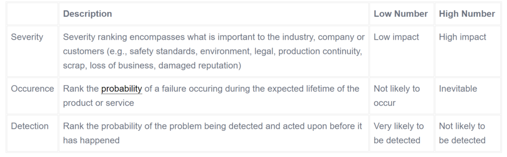
An FMEA uses three criteria to assess a problem:
1) The severity of the effect on the customer,
2) How frequently the problem is likely to occur and
3) How easily the problem can be detected.
Participants must rank the severity, occurrence, and detection level of each of the failure categories on a scale of 1 to 10 (1 = low, 10 = high). Despite the fact that FMEA is a qualitative procedure, it is critical to use data (where available) to qualify the team’s ratings determinations. The table below provides a more detailed explanation of the ratings.
After ranking the severity, occurrence and detection levels for each failure mode, the team will be able to calculate a risk priority number (RPN). The formula for the RPN is:
RPN = severity x occurrence x detection.
You will need to define a number that, if exceeded, requires a corrective action. Completing this corrective action will reduce the RPN number. After assessing all failure modes, the team should revise the FMEA to list failures in descending RPN order. This highlights the areas where corrective measures can be concentrated. If resources are limited, practitioners must prioritize the most serious issues first. There is no set RPN threshold for determining which areas should be prioritized; this is determined by a variety of factors, including industry standards, legal or safety requirements, and quality control.
Providing Recommended Actions :
When the priorities have been agreed upon, one of the team’s last steps is to generate appropriate corrective actions for reducing the occurrence of failure modes, or at least for improving their detection. The FMEA leader should assign responsibility for these actions and set target completion dates.
The FMEA is a valuable tool that can be used to realize a number of benefits, including improved reliability of products and services, prevention of costly late design changes, and increased customer satisfaction.
Setting up FMEA in the tool: (MagicDraw 19.0)
First of all make sure if the ‘Cameo safety and Reliability Analyzer’ plugin is installed in your tool. If not installed follow the below procedure to setup.
A. Download the plugin for MagicDraw 19.0 from the link below [https://www.magicdraw.com/main.php?ts=navig&cmd_show=1&NMSESSID=b2751cfbae4bd29d636d331140f14335&menu=download_all_in_one_plugins&back_cmd=cmd_show]
B. Open the MagicDraw tool→go to ‘Help’→Resource/plugin Manager
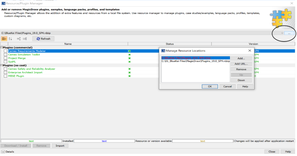
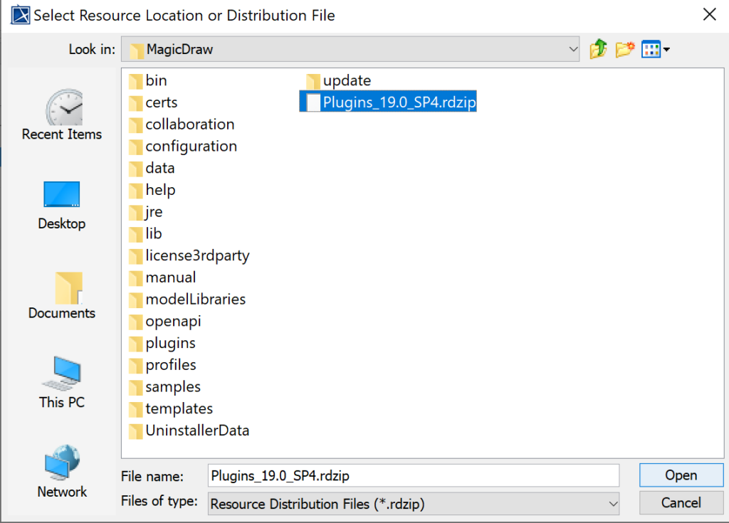
C. Click on the highlighted drop down menu→ Click Add→ Select the downloaded file & click Open→ Click ‘Ok’.
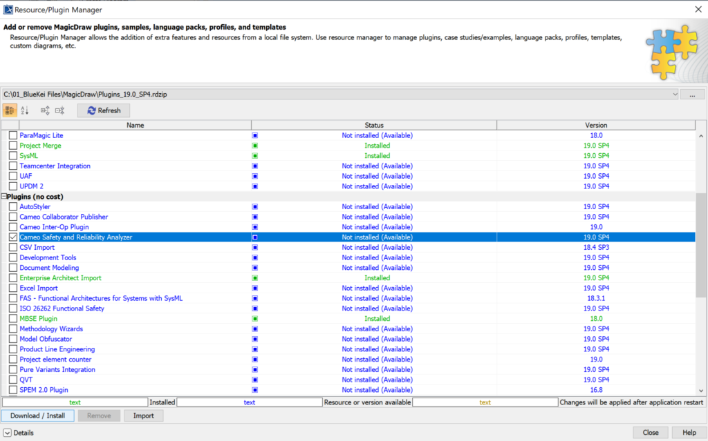
D. Select the ‘Cameo Safety and Reliability Analyzer’→Click on download/Install→ Click on Close and restart the MagicDraw tool.
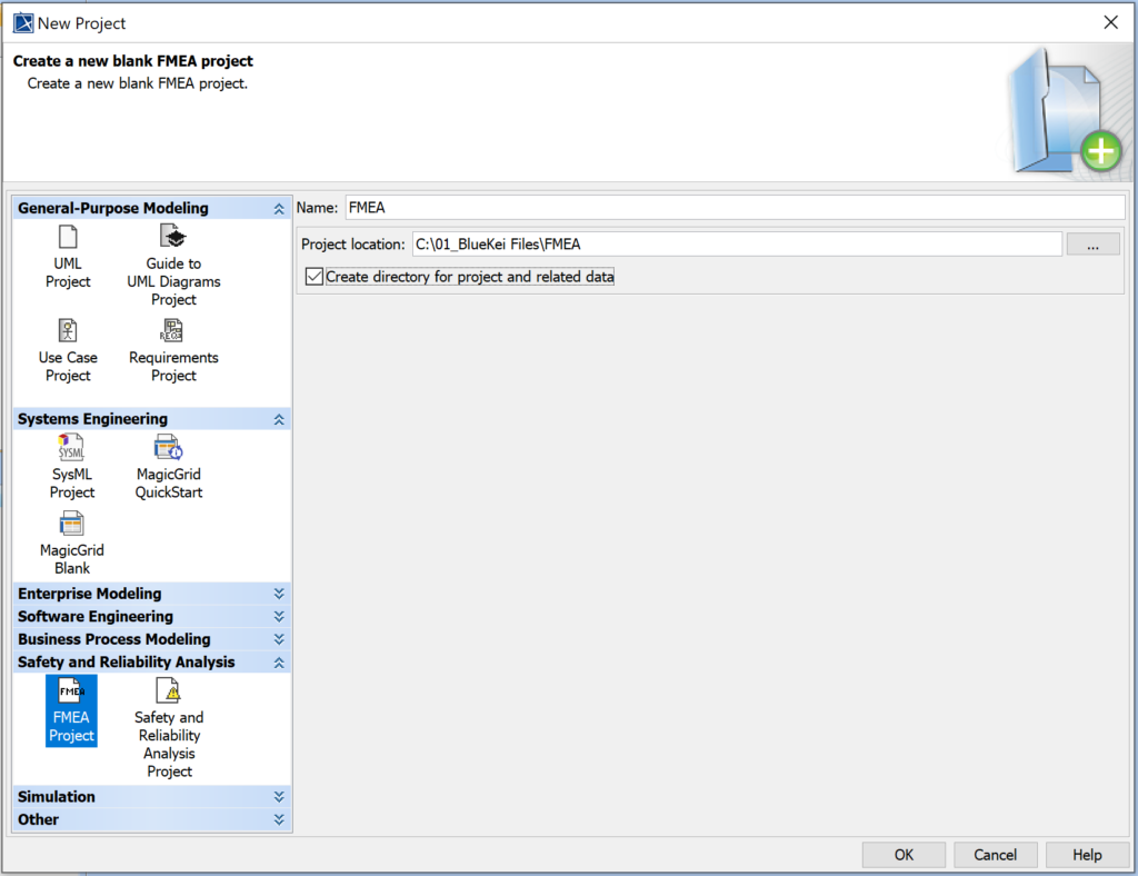
E. Open MagicDraw tool→ Select ‘FMEA Project’ from the options below→ Provide name, Project location & select the create directory option→ Click ‘ok’.
Here we begin,
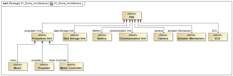
- Create a new BDD, IBD, Activity diagram or you can also use any previously created architecture which shows the system and its functions or components, wherein we perform FMEA for these elements.
Here in this example I have created a simple architecture of a Package Delivery Drone (as a system) and displayed a few subsystems/components of the system in the BDD.
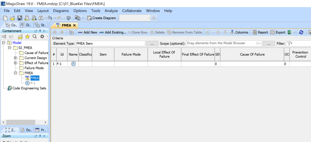
2. Expand the model packages in the containment tree→ In FMEA package, double click on the FMEA table→Click on ‘Add New’ from the menu bar. You can view the complete FMEA table with many attributes used to perform FMEA for any function/component. You can hide the columns and use the important columns as per your own preference.
3. Start filling out the details,
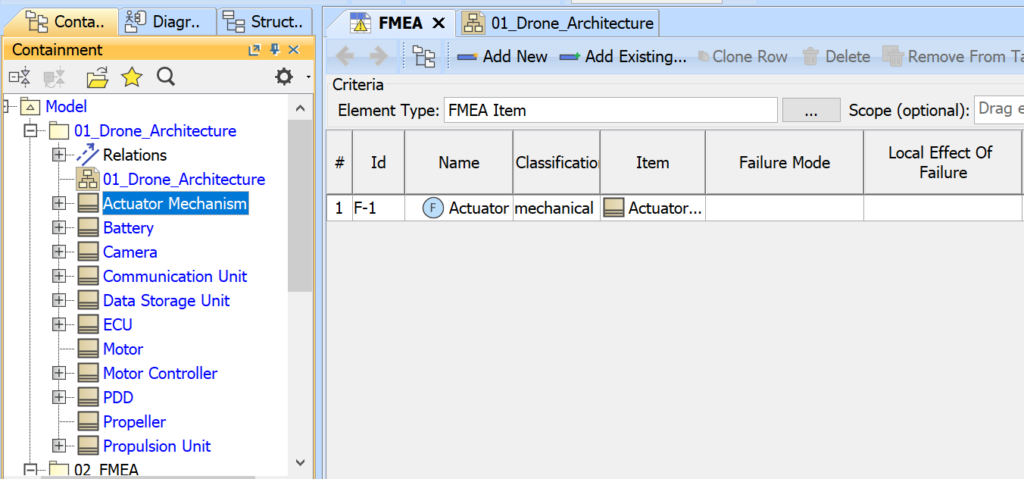
a. Provide the ‘Id number’ and ‘failure name’ for your component. In this example I have mentioned the failure name as ‘Actuator failure’ for the ‘actuator mechanism’ block/component.
b. Select the classification for your failure item i.e whether it is a mechanical/electrical/software related item.
c. For the ‘Item’ column you need to drag and drop the block/activity/part property which was created earlier to perform the FMEA. This artifact is now allocated as the FMEA item and all the other properties which we provide further will be allocated to the same artifact..
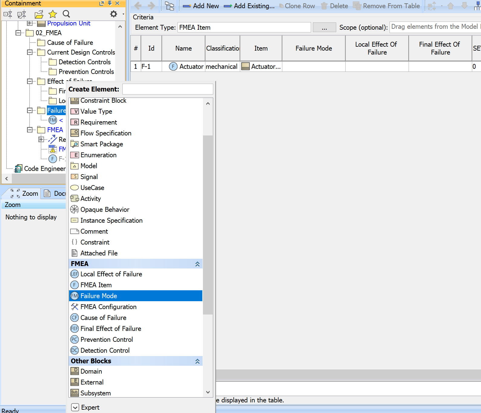
4. Now, for the ‘Failure Mode’ and other attributes you need to add separate items from the containment tree.
a. From the containment tree→ go to ‘Failure mode’ package→ Right click on the package→ Create element→ below under the FMEA elements select the ‘Failure mode’ item→ Provide the failure mode to the item.
b. Once you write the details of failure mode simply drag and drop the ‘FM item’ onto the Failure mode column.
c. Similarly you need to follow the same steps for the other columns/attributes.
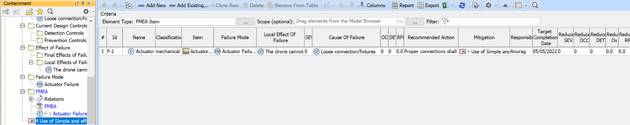
5. Once you complete few of the columns with the FMEA items,
a. Now we need to provide ‘Recommended Action’ by simply typing in that particular column.
b. Next we have ‘Mitigation’, here we need to create a requirement artifact from the containment tree.
Right click on the FMEA package→ create element→ select Requirement→ Write the ‘Mitigation plan’ for the Failure item in the Requirement box/artifact.
Now, Drag and drop the ‘Mitigation Requirement’ onto the Mitigation column.
6. Now, it’s time to fill in the Severity, Occurrence and Detection columns for the FMEA item. You can directly type the numbers from 1-10 in these columns. For more details please refer to ‘Table 1’.
a. The Severity number in my example for ‘Actuator failure’ is given as ‘6’
b. The ‘Actuator failure’ is less likely to occur, so I would provide the number as ‘3’
c. The ‘Actuator Failure’ can be detected and acted upon at earliest, so I have provided the number as ‘3’.
d. Now, the RPN (Risk Priority number) is obtained which is automatically calculated in this tool. The RPN provides us a relative risk ranking, higher the RPN, higher the potential risk.
e. In some cases, it may be appropriate to revise the initial risk assessment based on the assumption (or the fact) that the recommended actions have been completed. This provides an indication of the effectiveness of corrective actions and can also be used to evaluate the value to the organization of performing the FMEA. To calculate revised RPNs, the analysis team assigns a second set of Severity, Occurrence and Detection ratings for each issue (using the same rating scales) and multiplies the revised ratings to calculate the revised RPNs
f. Similarly you need to follow the same steps for the other components.
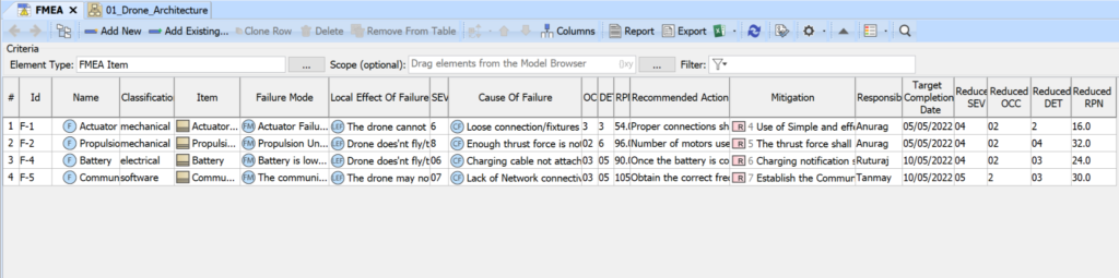
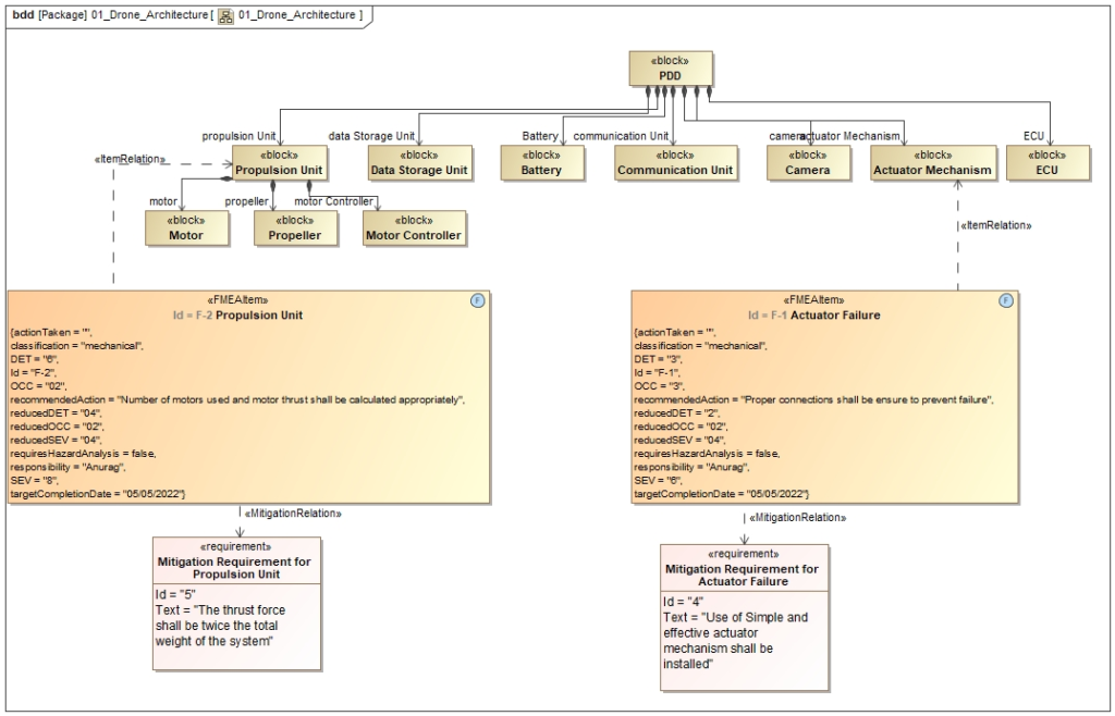
7. Once you perform the FMEA for various components/subsystems, the entire FMEA data gets linked with the component/subsystem & you can extract the information in other SysML diagrams as well such as BDD.
Right click on the block used as FMEA item→ Display→ Display related elements→ Click ‘Ok’
Conclusion:
SysML is a general-purpose architecture modeling language designed for use in System Engineering applications. SysML allows for multiple views while maintaining consistency across all of them. When the entire system is built/developed using MBSE tools and the connectivity/traceability is established, it creates a gap when the FMEA is performed outside of the tool or in some spreadsheets. We can perform FMEA and establish traceability across system artifacts using MBSE tools or SysML, and you can easily view the FMEA data within various diagrams such as Block definition diagrams and generate traceability views.
We can tailor the FMEA table, FMEA items, and other artifacts to the needs of the company, and we can also produce hazard risk analysis tables within MBSE tools.
If you are interested in understanding how to apply this approach within your organization, reach out to us at info@Blue-Kei.com. At BlueKei we specialize in systems engineering consulting, project executions, process adoptions, digital transformations and conducting workshops which are experiential and tailored to your needs. With systems engineering adoption you can address the complexity, manage evolving risks and bring transformation in communication within your organization through digitalization.