At the vanguard of technical innovation, aerospace systems engineering adds a new level of complexity with each advancement in aviation and space exploration. This degree of complexity is organizational in nature as well as technical, involving the complex design, integration, and testing of extreme...
The rise of Agile Systems Engineering reflects an understanding of the current dynamic project environments and the need for innovative solutions to complex challenges. Enter Agile Systems Engineering, a methodology that marries the flexibility of agile principles with the rigor of systems engineeri...
In a world driven by swift technological breakthroughs, two systems set out on a journey: a Decision-Making System and a System aimed to benefit humanity. Their objective was to figure out the secrets of the other, Human Factors Engineering (HFE), and incorporate them into the very fabric of their b...
Introduction: In this age of rapid technological development, systems engineering is going through a significant transition. The modern need for agility, adaptability, and fast change response puts established methods to the test. In-depth discussion of Agile Systems Engineering (ASE) and its critic...

Introduction: If you want to build a complex system, you need to use project management and systems engineering, together. There is a lot of research and documentation systems engineering and project management. If the systems engineer and project manager work together well, the project is more l...
Introduction: In the dynamic landscape of modern engineering, the development of complex systems, especially in the automotive and aerospace industries, demands innovative approaches that can handle the intricacies of integration, optimization, and scalability. Two key methodologies, Systems Enginee...

Introduction: In the ever-evolving landscape of the automobile industry, the demand for electric vehicles (EVs) has surged, driven by the need for sustainable and eco-friendly transportation solutions. A critical component in the development of electric vehicles is the Battery Management System (BMS...

The roar of the engine, the wind in your hair, the freedom of the open road…cars have fueled our dreams of adventure for generations. But in the age of interconnected technology, a new element has joined the journey: cybersecurity. Cybersecurity is rapidly growing as a critical and constantly ...
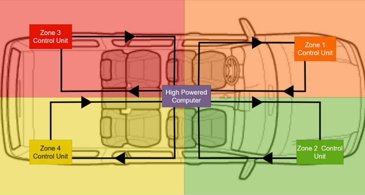
A Software-Defined Vehicle (SDV) represents a significant departure from traditional automobiles, where reliance on hardware predominantly shapes their characteristics. SDVs leverage software to define and control their functionalities, introducing a paradigm shift in the rapidly evolving landscape ...