A systems engineer’s perspective on Chandrayaan-3 development
Chandrayaan-3 represented subsequent mission following the Chandrayaan-1 and Chandrayaan-2 endeavors for lunar exploration. It was launched on July 14th 2023, mere four years after Chandrayaan-2’s unsuccessful attempt to achieve a soft landing in the moon’s south polar region. In an informative session hosted by the Indian Institute of Science (IISC), Bangaluru on August 5th, 2023, Chairman of the Indian Space Research Organisation (ISRO), S. Somanath, took the stage to provide a detailed explanation of the anomalies encountered during Chandrayaan-2 and the subsequent corrective measures implemented in Chandrayaan-3.
The investigation revealed that the root cause of the anomaly in Chandrayaan-2 was attributed to a software system designed to manage a multitude of variables emanating from all onboard systems during the critical fine braking phase. This software system encountered challenges in compensating for uneven thrust, ultimately resulting in the mission’s unfortunate crash. Subsequent to the establishment of a Failure Analysis Committee, a series of comprehensive analyses, including Failure Analysis, Root Cause Analysis, and Fault Tree Analysis (FTA), were meticulously conducted to understand the intricacies of the issue and to inform the corrective actions for Chandrayaan-3.
What now?
With the report of Root Cause Analysis, the designated team started identifying:
A. Systems which worked perfectly well
B. Systems which worked fine but can be modified
C. Systems which needed to be made robust or change the mechanism of those systems or Addition of new systems to perform the functions.
Following the identification of these systems, the systems that performed exactly as expected (“System A”) were baselined and did not require any changes. The systems that required minimal modifications or complete replacement (systems B & C) were also identified. Impact analysis and change management were then carried out to identify additional elements that would be impacted by these changes.
The requirements, architectural components, and design of [“System A”] in a system engineering context would stay the same, but the prior tests conducted on these systems would be somewhat similar.
The parametric analysis was now carried out on the second category [“System B”] to determine if the intended adjustments would be in line with the permitted mission budget or not.
Extensive analysis was performed on the third category [“System C”] to determine what all new additions needed to be made to correct prior failures, after which the overall development was started with “Failure based design” using simulations like Monte Carlo, etc. Potential failure conditions were identified for each system, and as a result, the development of these systems was ensured for robustness.
The overall impact analysis and Change management provided insights on allowable constraints, example: Since Chandrayaan-2 had already placed an orbiter, there was extra allowance for weight to be carried. This allowed for adding weight to the lander module in the form of additional fuel allowance, but with that the lander legs will have to withstand higher impact. Such scenarios were considered.
Following the conclusion of the identification of the three system categories, it was necessary to assess and update the requirements for [“System B”] with respect to Chandrayaan-2 and to derive requirements for [“System C”] in accordance with the identified changes.
For example:
1. For System ‘B’ type Guidance Control Range was preset to 10°/sec in Chandrayaan-2 and was updated to 25°/sec in Chandrayaan-3.
2. For System ‘C’ type there was the absence of a dedicated Velocity measurement unit aboard Vikram lander in Chandrayaan-2 but was highly dependent on other onboard instruments, while it did not contribute to the anomaly during landing, a dedicated instrument was developed and went aboard Vikram lander in Chandrayaan-3 which provided accurate measurements of velocity in all directions.
Architecture and design changes:
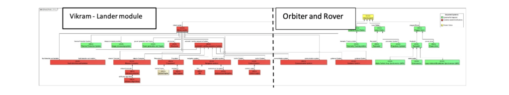
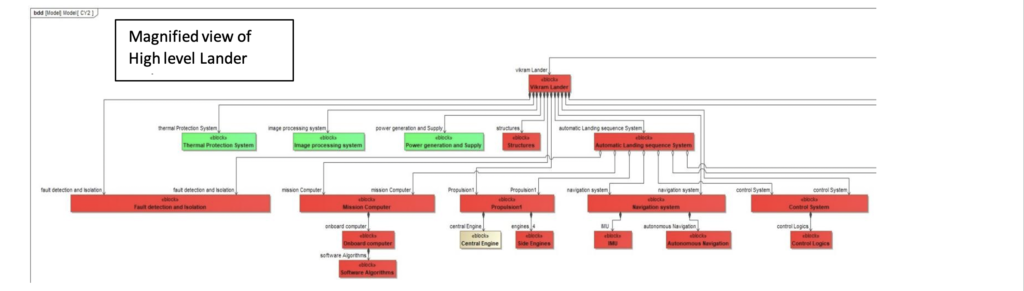
The diagram above illustrates the systems that experienced adverse impacts, indicated in red, during the automatic sequence landing. Conversely, the systems that performed as expected are denoted in green. The components in the green category will remain unchanged and will not undergo any alterations. However, one element warrants special attention: the central engine. After a meticulous evaluation of all available options, there is a possibility that it may be removed and replaced with a new fuel tank.
The development of architecture and design commenced after identifying the elements that required modification and those slated for removal. This process was carried out with careful consideration of the impacts associated with these changes. Following the architectural development, steps were taken to ensure that the modifications did not adversely affect the elements marked in green, utilizing a dependency analysis.
Subsequently, a new version of the architecture with the implemented modifications is depicted below.
V&V:With change in Requirements, architecture and design, they must undergo a series of testing in order for the systems to be verified. In the conference held in IISC Chairman, ISRO mentioned that the testing team had introduced new test cases in simulations through various test beds. As a part of verification program, the team also had set up an additional test bed (Software-in-Loop-SILS) to accommodate 6 Degree of freedom to check integrity of flight software and a new Test setup in URSC for impact landing.
Additional test cases focused on simulating the stress level of software for worst case scenario and checking how the systems respond through computational triggering. Thorough simulation trials on the conditions identified through Monte Carlo to ensure fail proof. A few special tests were also planned and conducted successfully such as Cold and hot firing tests of Lander and Propulsion systems. A separate simulation model to test orbital parameters and the behavior of the entire Chandrayaan-3 module, such as Earth-bound maneuvers, Translunar insertion, Lunar orbit insertion, and Descend path till surface.
A separate simulation model to test orbital parameters and the behavior of the entire Chandrayaan-3 module, such as Earth-bound maneuvers, Translunar insertion, Lunar orbit insertion, and Descend path till surface.
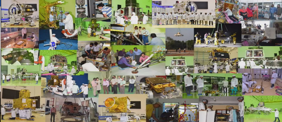
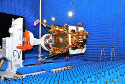
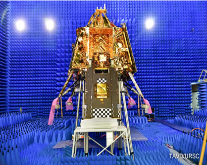
The images below show the various levels of testing being carried on all units of Chandrayaan-3, it was ensured that from previous learnings and newly thought scenarios, extensive testing was carried out throughout the program to ensure the capability to land and deploy rover safely.
Additional test cases focused on simulating the stress level of software for worst case scenario and checking how the systems respond through computational triggering. Thorough simulation trials on the conditions identified through Monte Carlo to ensure fail proof. A few special tests were also planned and conducted successfully such as Cold and hot firing tests of Lander and Propulsion systems. A separate simulation model to test orbital parameters and the behavior of the entire Chandrayaan-3 module, such as Earth-bound maneuvers, Translunar insertion, Lunar orbit insertion, and Descend path till surface.
A separate simulation model to test orbital parameters and the behavior of the entire Chandrayaan-3 module, such as Earth-bound maneuvers, Translunar insertion, Lunar orbit insertion, and Descend path till surface.
The images below show the various levels of testing being carried on all units of Chandrayaan-3, it was ensured that from previous learnings and newly thought scenarios, extensive testing was carried out throughout the program to ensure the capability to land and deploy rover safely.
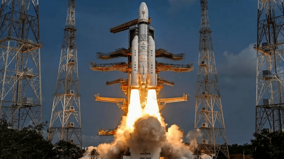
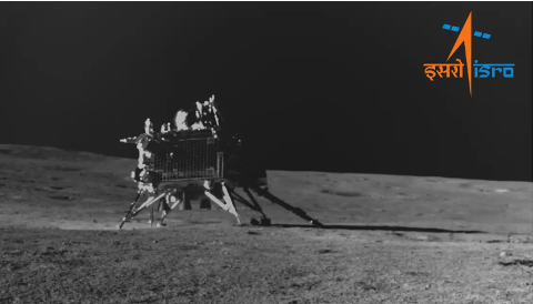
After 4 long years of consistent work on July 14th at 14:35 hours IST the LVM – MK3 launched with Chandrayaan – 3’s Propulsion and lander module, on August 23rd 18:04 hours IST. The Chandrayaan-3 made history by becoming the first to land on South polar region of moon.
Post Views: 46